
This tutorial will show you how to use FRED — a cloud-based Node-RED — to control and read data from Arduino boards using an ESP8266 module and the STS-MQTT platform. The ESP8266 is a popular, low cost Wifi module with a full TCP/IP stack and microcontroller. In this tutorial we are using the ESP8266-01 module along with the Arduino UNO. For demo purposes, we are using a DHT 22 temperature and humidity sensor to provide data.
We have provided detailed sample code here. If you do not know how to import flows, you can refer to this article.
Create a FRED Account
If you don’t already have an account on FRED (Cloud Node-RED), set one up now. Register at http://fred.sensetecnic.com.
After registering, make sure to activate your account via your email. You will not be able to log in until you validate your account.
About Sense Tecnic: Sense Tecnic Systems has been building IoT applications and services since 2010. We provide FRED, cloud hosted Node-RED as a service to the community. We also offer a commercial version to our customers, as well as professional services. Learn more.
Prerequisites
To try out this tutorial with FRED, you will need the following software and services:
- If you don’t already have a FRED account, set one up. Note that you will need to subscribe to a paid plan to use the STS-MQTT platform.
- The Arduino IDE installed on your workstation. You can refer to this document from the official Arduino website on how to install it.
You will also need the following hardware components
- An Arduino UNO board
- An ESP8266-01 board
- A Bi-Directional level shifter to convert voltage level between Arduino and ESP8266-01
- A DHT 22 sensor
- A LED
- 1K Ohm Resistor
- 3.3v external power supply (I used two AA batteries)
- A breadboard
Outline of the tutorial
- Connect Arduino UNO to ESP8266-01 for initial testing
- Connect Arduino UNO to ESP8266-01 and other sensors
- Set up the connection on STS-MQTT platform
- The Arduino sketch
- Connection on STS-MQTT and FRED
Connect Arduino UNO to ESP8266-01 for initial testing
We will need to setup the ESP8266-01 for this tutorial. First, let’s connect the Arduino UNO to ESP8266-01 like this:
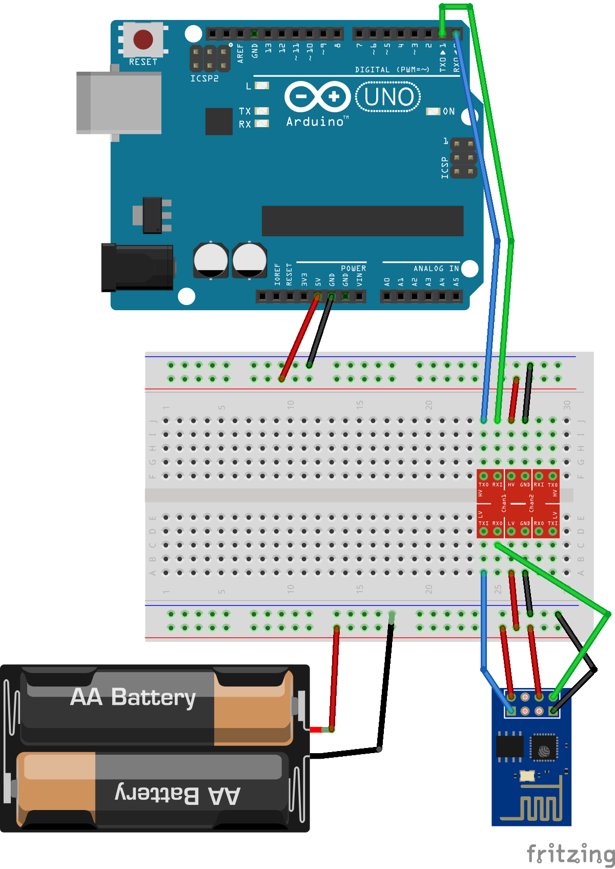
As you can see, we use the Bi-Directional level shifter to convert the communication signal between the ESP8266-01 and Arduino-UNO. The ESP8266-01 can only take 3.3v as input, but the Tx/Rx port on the Arduino board uses 5v. It is safer to use the level shifter to protect your ESP8266-01 module and also prevent signal errors.
Also, notice that the ESP8266 module draws more current than the Arduino UNO 3.3v output can support, so using an external power supply can protect the circuit as well as providing a more reliable performance. In this case, we used two AA batteries and that works like a charm.
With this set up, just open the BareMinimum sketch from the examples and upload to Arduino UNO,
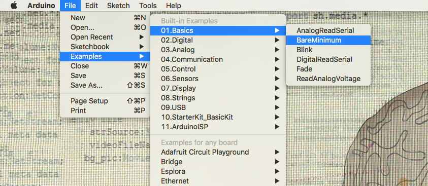
Once uploaded, open the Serial Monitor from the tools menu.
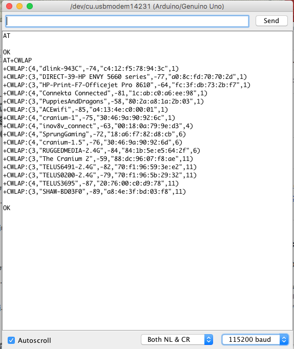
You will need to set the serial monitor to “Both NL & CL” in the bottom dropdown menu. The baud rate depends on the module you get. The default baud rate on my module was 115200. You will have to get the correct baud rate in order to read proper characters on the serial monitor. To see if the module is connected correctly, enter “AT” in the serial monitor and send. If the serial monitor returns “OK” then your ESP8266 is responding to your command.
Here is a list of the AT command that you can send to the ESP8266 module at this point. For example, if you enter “AT+CWLAP”, the ESP8266 module will return a list of available wifi networks. NOTE: there should not be any spaces in the AT commands.
For this tutorial, since we are using the WiFiEsp library and the pubsubclient library, it is required to change the baud setting for the ESP module to a much lower rate. We will send this command in the serial monitor:
AT+UART_DEF=9600,8,1,0,0
which will set the ESP module to use 9600 baud rate / 8 data bits / 1 stop bits and no parity bit or flow control.
Now you can try the test command above in the serial monitor with 9600 baud rate to verify the change.
Connect Arduino UNO to ESP8266-01 and other sensors
Now we will setup the actual circuit for this project.
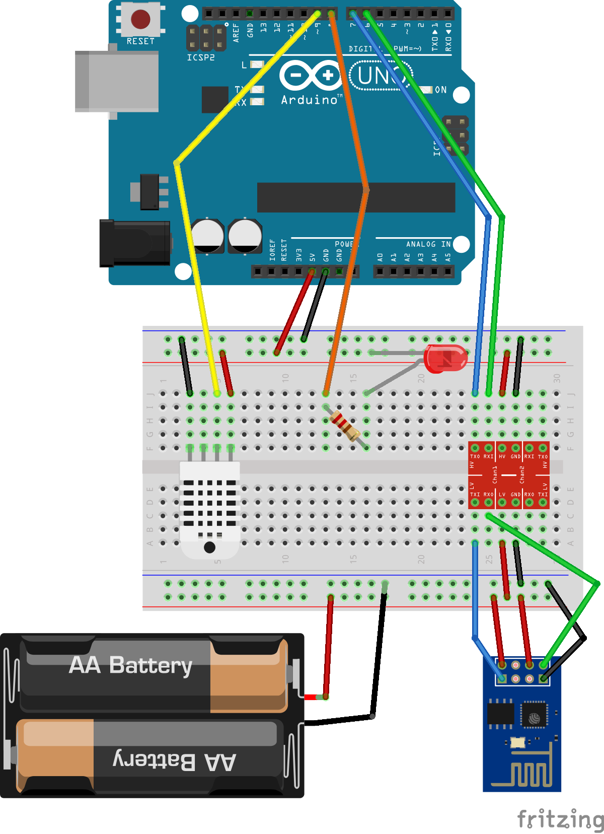
As you can see in this diagram of the second phase, the wiring on the Arduino UNO board has changed quite a bit. You will need to move the cables connecting the Tx/Rx ends to different digital pins in order to communicate with the ESP module properly. In this project, we also added a DHT22 sensor as data input, and a LED to demonstrate data output.
Set up the connection on STS-MQTT platform
Now we need to set up the MQTT connection on STS-MQTT platform. Note that you will need a paid plan in order to create clients on the STS-MQTT platform.
To find out more about the STS-MQTT platform and how to create clients or topics, please refer to this tutorial.
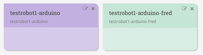
In this tutorial, we will need two clients, one for the Arduino UNO, and one for FRED. Here are the two clients I created:
We will also create four topics. They are:
users/<YOUR USERNAME>/arduino/status
users/<YOUR USERNAME>/arduino/send/temperature
users/<YOUR USERNAME>/arduino/send/humidity
users/<YOUR USERNAME>/L                            //We will explain this topic in the later section
The Arduino sketch
Now we will need to write some code for the Arduino UNO!
Before you start, you will need to get three libraries. They are:
pubsubclient by Nick O'Leary                https://github.com/knolleary/pubsubclient
WiFiEsp by Bruno Portaluri                  https://github.com/bportaluri/WiFiEsp
DHT-sensor-library by Adafruit              https://github.com/adafruit/DHT-sensor-library
To install libraries for Arduino, you can refer to this document.
Once you’ve installed the libraries, we can go ahead to edit the code.
Here is the example code of the sketch. You can start a new sketch and copy this code in the Arduino IDE:
[cc lang="c"escaped="true" tab_size="2"]
#include <WiFiEsp.h>
#include <WiFiEspClient.h>
#include <WiFiEspUdp.h>
#include "SoftwareSerial.h"
#include <PubSubClient.h>
#include "DHT.h"

#define ESP_SSID                                      "Your SSID"
#define ESP_PASS                                      "Your Wifi Password"

#define mqtt_server                                   "mqtt.sensetecnic.com"
#define mqtt_port                                     1883
#define mqtt_client_id                                "Your MQTT Client ID"
#define mqtt_client_user                              "Your STS Username"
#define mqtt_client_pw                                "Your MQTT Client Password"
#define mqtt_client_topic_send_status                 "users/<Your Username>/arduino/status"
#define mqtt_client_topic_send_temperature            "users/<Your Username>/arduino/send/temperature"
#define mqtt_client_topic_send_humidity               "users/<Your Username>/arduino/send/humidity"
#define mqtt_client_topic_receive_led                 "users/<Your Username>/L"
#define birthMsg                                      "Arduino Client connected"
#define willMsg                                       "Arduino Client disconnected"

#define LEDpin 8
#define DHTPIN 9
#define DHTTYPE DHT22
DHT dht(DHTPIN, DHTTYPE);

String temp_str;
String hum_str;
char temp[50];
char hum[50];
float humidityReading; //Stores humidity value
float temperatureReading; //Stores temperature value
long lastMsg = 0;
long lastLoop = 0;

int status = WL_IDLE_STATUS; // the Wifi radio's status

WiFiEspClient espClient;

//print any message received for subscribed topic
void callback(char* topic, byte* payload, unsigned int length) {
  Serial.print("Message arrived [");
  Serial.print(topic);
  Serial.print("] ");
  for (int i=0;i<length;i++) {
    Serial.print((char)payload[i]);
  }
  Serial.println();
  if((char)payload[0] == '1') {
    Serial.println("LED is on");
    digitalWrite(LEDpin, HIGH);
  } else if ((char)payload[0] == '0'){
    Serial.println("LED is off");
    digitalWrite(LEDpin, LOW);
  }
}

PubSubClient client(mqtt_server, mqtt_port, callback, espClient);

SoftwareSerial soft(6, 7); // RX, TX

void setup() {
  // initialize serial for debugging
  Serial.begin(9600);
  // initialize serial for ESP module
  soft.begin(9600);
  // initialize ESP module
  WiFi.init(&soft);

  dht.begin();
  pinMode(LEDpin, OUTPUT);

  // check for the presence of the shield
  if (WiFi.status() == WL_NO_SHIELD) {
    Serial.println("WiFi shield not present");
    // don't continue
    while (true);
  }

  // attempt to connect to WiFi network
  while ( status != WL_CONNECTED) {
    Serial.print("Attempting to connect to WPA SSID: ");
    Serial.println(ESP_SSID);
    // Connect to WPA/WPA2 network
    status = WiFi.begin(ESP_SSID, ESP_PASS);
  }

  // you're connected now, so print out the data
  Serial.println("You're connected to the network");
}

void sendData() {

  humidityReading = dht.readHumidity();
  // Read temperature as Celsius (the default)
  temperatureReading = dht.readTemperature();

  Serial.print("Humidity reading: ");
  Serial.println(humidityReading);
  Serial.print("Temperature reading: ");
  Serial.println(temperatureReading);

  if (isnan(humidityReading) || isnan(temperatureReading)) {
   Serial.println("Failed to read from DHT sensor!");
   return;
  }

  temp_str = String(temperatureReading);
  temp_str.toCharArray(temp, temp_str.length() + 1);

  hum_str = String(humidityReading);
  hum_str.toCharArray(hum, hum_str.length() + 1);

  client.publish(mqtt_client_topic_send_temperature, temp);
  client.publish(mqtt_client_topic_send_humidity, hum);

}

void loop() {

  long now = millis();

  if (now - lastMsg > 15000) {
    lastMsg = now;
    sendData();
  }

  if (now - lastLoop > 200) {
    lastLoop = now;
    if (!client.connected()) {
      reconnect();
    }
    client.loop();
  }
}

void reconnect() {
  // Loop until we're reconnected
  while (!client.connected()) {
    Serial.print("Attempting MQTT connection...");
    // Attempt to connect, just a name to identify the client
    if (client.connect(mqtt_client_id, mqtt_client_user, mqtt_client_pw, mqtt_client_topic_send_status, 1, 1, willMsg)) {
      Serial.println("connected");
      client.publish(mqtt_client_topic_send_status, birthMsg);
      Serial.println(client.subscribe(mqtt_client_topic_receive_led));

    } else {
      Serial.print("failed, rc=");
      Serial.print(client.state());
      Serial.println(" try again in 5 seconds");
      // Wait 5 seconds before retrying
      delay(5000);
    }
  }
}
[/cc]
You will need to fill in the details of your own wifi network SSID/password and your MQTT authentication information in order to make the code work. Once you finish the modification, simply compile the code and upload to Arduino.
Here is the explanation of the code. In setup(), the Arduino board will first initial the ESP module and try to connect to the Wifi network specified with ESP_SSID and ESP_PW. Once the ESP module is connected to the network, the pubsubclient client will then try to connect to the MQTT broker that you provided. If all connections succeed, the Arduino UNO board will start its job to:
- Publish birth and will messages to the “status” topic
- Report the temperature and humidity data every 15 seconds
- Subscribe to the “L” topic (the serial monitor will print out the return value of the subscribe function where 1 is success and 0 is fail)
Note that there have been reported issues on subscribing to MQTT topics using the pubsubclient and WiFiEsp. Since there are several variations of ESP8266 modules out there so you might not experience the same issue. If you have better solutions to solve these issues, please let us know by emailing us at info@sensetecnic.com. The main issue is discussed here. After some experimentation, we were able to improve the rate of receiving subscription messages as follows:
In the pubsubclient library, you will need to modify the loop() function in PubSubClient.cpp to remove an IF statement that checks whether the client is connected. The connected() function returns if the client is connected or not, but it takes some time to return the result. If we comment out the following three lines:
boolean PubSubClient::loop() {
    // if (connected()) {
        ......
        return true;
    // }
    // return false;
}
The success rate to receiving a message from the cloud server will be much higher. At this point, you will need to make sure that your client.loop() function is not called when the client is not connected.
Also as discussed in here, long topic names might cause errors in receiving incoming messages. Thus we used “users/<YOUR USERNAME>/L” as that is the shortest possible topic name on the STS-MQTT platform.
Also, as discussed above, you will need to add some time interval between each call to the client.loop() function. Several users have reported using 100ms, but in our experiments, we found 200ms works better. We encourage you to try different values and find which value works the best for you. Here is how we set the time interval in the main loop() function in the Arduino sketch:
 if (now - lastLoop > 200) {
   lastLoop = now;
   if (!client.connected()) {
    reconnect();
   }
   client.loop();
 }
Also you should try to avoid sending rapid messages to the Arduino board as discussed here. With our settings, we found that sending one message approximately every three seconds apart works fine.
Connection on STS-MQTT and FRED
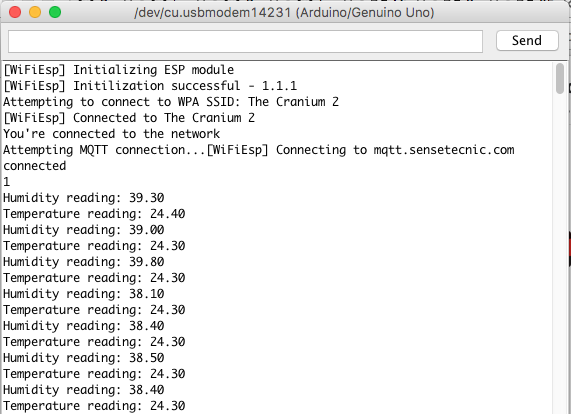
Once you are able to see the Arduino serial monitor reporting data from the DHT22 sensor, we can log on the STS-MQTT platform to verify the incoming data. To find out more about using the STS-MQTT dashboard as a debug tool, please refer to this tutorial.
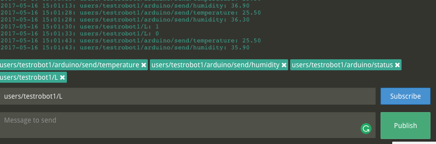
Once you subscribe to the channel you specified in the Arduino sketch, you should see the data coming in:

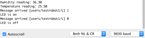
You can also control the LED from the dashboard. Simply publish ‘1’ or ‘0’ to the topic “users/<YOUR USERNAME>/L” (as we defined in the sketch), and you should see the LED turning on and off.
And you should see this in the serial monitor.
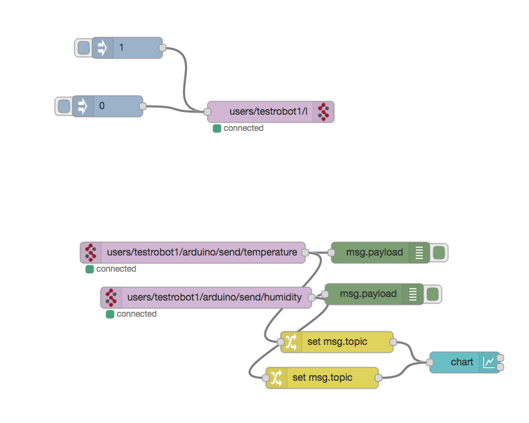
We can set up a very simple flow on FRED that will send ‘On’ and ‘Off’ command, and also draw the received data onto a dashboard.
and the dashboard diagram will look like

The change in the graph was due to the sunlight after some rain. The weather in Vancouver can change quickly!
About Sense Tecnic: Sense Tecnic Systems Inc have been building IoT applications and services since 2010. We provide FRED, cloud hosted Node-RED as a service to the community. We also offer a commercial version to our customers, as well as professional services. Learn more.